Negative Problems: Astro City -5v Supply Issues

Problems are inherently negative, but I digress;

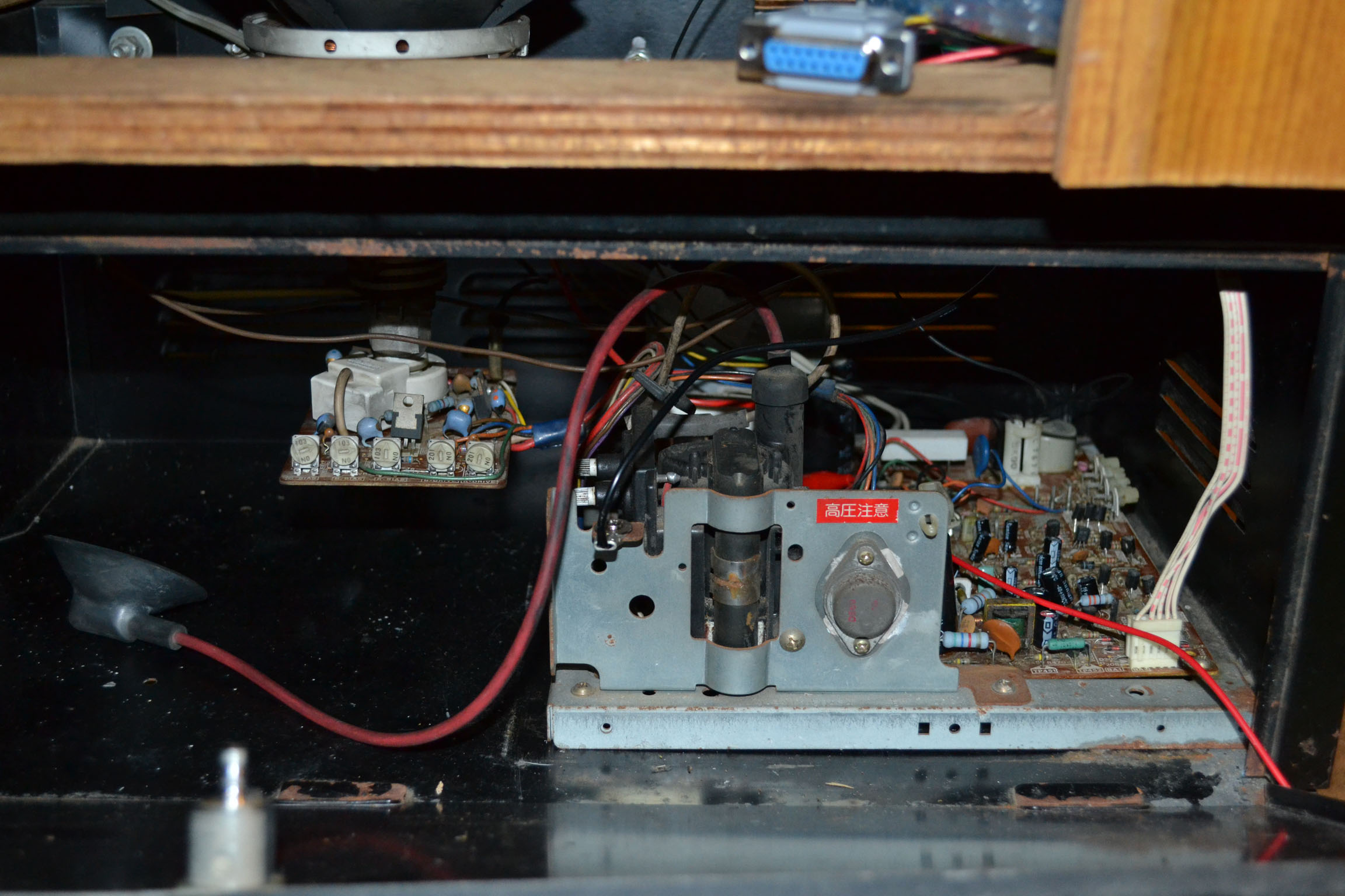
The two schematics attached above are the schematics of two relatively common power supply types that you’ll find in an Astro City, or New Astro City cab. The left one (mostly illegible, sorry) is the 400-5198-01Y PSU – a bog standard, weak-ass Astro stock PSU. The right one is the 400-5261 PSU, reportedly more common in a New Astro City.

I have the NAC supply (400-5261X – though there are some variants), and as you can imagine I was fairly disappointed when I found my Mortal Kombat boards (2 and UMK3) had begun operating with merely a faint buzzing instead of the searing commentary you’ll find from the commentator. They require a -5v supply and if it’s missing, buzzing is all you’ll get out of them (and in the case of Mortal Kombat 3, you might get ROM errors).

The -5v kind of just dropped off one day, but after 18 months of procrastinating I’ve finally had time to revisit it. Now I can summarise the problem for those of you playing at home: It’s probably the transistor at IC3 in the 400-5261 supply.  A similar troubleshooting guide for the 400-5198-01Y can be found here, but it says much the same.

The transistor is a 78L05. And the problem is it’s an apparently weak supply to begin with. So if your fatality draws too much current for some reason you can wave the transistor goodbye.

A check with a multimeter on the -5V line on mine at the time revealed it was putting out nil. Nada. Zip. Later on, it started emitting a mild hissing sound occasionally… The point is, there was clearly a problem.

The internet (KLOV for one) generally seems to recommend doing a cap kit on these power supply’s as sort of general advice if it’s never been done before, but when I opened mine yesterday I found they were totally fine and not at all leaky. Results may vary.

The transistor in question is clearly marked and located near the heatsink at the half-way mark of the PCB on my particular unit. The PCB had clearly seen some heat during its time, resulting in sort of a darker colour around that area on the solder side – be careful not to apply too much heat and lift the pads off the circuit board during the process of removing the transistor. A fuck up can be salvaged by using the longer legs of a new transistor, pushed over and soldered to pads on the same traces nearby, but ideally you just want to avoid that sort of issue entirely.

ac-psu-circled

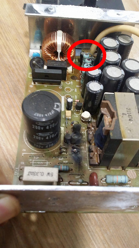
Please ignore this person’s unfortunate scorch marks, because I didn’t take any photographs of my own during this repair process… IC3 is located around the circled area.

I procured a replacement 78L05 transistor and finally got the party started. I put it all back together and fired up the cabinet with no board attached to get a reading. It’s hard to get an accurate reading with no board load attached, but more than nil was all I was aiming for in this case – would you risk your increasingly expensive Mortal Kombat boards? At anyrate, a line reading with no board attached was hovering around -3.8v. Bingo!

Even though that figure is lower than I was hoping to see, it was enough for me to risk everything and hook UMK3 up. And with one bell sound I knew I was good to go. For now.

If the voltage is reading far lower than that, or still nil, there are other problems in that circuit. Thankfully it’s fairly basic, and standard basic electronic troubleshooting should help you get to the bottom of it.

The Sanyo EZZ-C 14-inch Colour Monitor: The 20EZ’s neglected 14″ cousin.

I recently came into possession of an original Taito Space Invaders cocktail that needed some attention. All over, infact – it’s pretty far from ‘original’. The internal wiring was a bit of a mess to say the least. The 36-pin connector conformed to no known profile (I imagine it was just generically wired so a breakout board would quickly fit it to other games), the control panels were hanging by their own wiring and the CRT was in a sad state, though still somewhat functional. Having seen how far from original the wiring was already, I made the decision to just convert to JAMMA. DSC_1186

Still very much a work-in-progress as you can see.

Put simply, the whole thing was caked inside and out with dirt and needed to be rewired, recapped, repainted and just generally sorted out – abused over many years at many-a-milkbar no doubt.

I made a decision to continue with my theme of quick-connects for the Control Panels after I cut away the last lifelines (read: three wires) that were holding the Player 1 side controls to the cabinet. The bolts were long gone. As I learnt from another cocktail project currently on a site, not being able to easily remove the control panels to replace/maintain them is a pain in the ass. Hence the DB-15 connectors you see hanging in the previous pic.

DSC_1191

Freshly repainted plastic, awaiting the express-package of new controls from Japan that have been stuck in Australian customs for 3-weeks now.

The CRT chassis also needed the same kind of treatment after I realized the AC was hardwired into the isolation transformer. At anyrate:


The Sanyo EZZ-C Chassis Quick Info Sheet

Chassis Map Extract

CRT: 14 Inch – Sanyo 370HAB22

AC: 100v

B+ Test Point: TP91/BJ

B+ Target: 108v

B+ Pot: 5k Ohm

IC601: Sanyo LA5112N IC (9-Pin Voltage Regulator)

TR901: 2SD1090 (3-Pin Current Limiter)

No Remote or Audio Board

Closest relative: Sanyo EZ20

DSC_1183

For all intents and purposes, this thing barely fucking exists on the internet. Sure, there’s a few confused postings on KLOV and similar places, but I basically had to scramble information from everywhere to find out what I was looking at. I was initially misled by an Atari document for a “14” Sanyo Color Monitor” that also didn’t match what I had. Moreover, the well known 20EZ cap kit is not correct for this chassis. Similarly, the name of the chassis was hidden on the dirty frame, so naturally I worked that out after I had lazily printed and filled the 20EZ list.

Chassis B4

It was pretty dirty before I had it out.

The 14″ chassis IS similar to the 20EZ in a number of ways, particularly the circuit board layout, though at least a dozen caps are different. These are the differences I identified (though your mileage may vary):

C201                      16v 220uF

C301/C303/C406     50v 10uF

C408/C467/C610     160v 1uF

  C409                     160v 10uF

 C464                      50v 22uF

    C469                      25v 220uF

     C489                      25v 330uF

        C606 (Filter cap)    160v 470uF

That filter cap is important to note because it typically isn’t included in the normal cap kit lists. Well documented 20EZ problems like the “flag waving” picture post-recap also apply to this chassis (and applied to mine – currently waiting on the replacement for that also). C606 is responsible for that problem much of the time.

A quick listing of other pots you may like/need to replace:

VR451 – H Hold – 3K Ohm

VR302 – Bright – 10k Ohm

VR401 – V Hold – 200K Ohm

VR402 – V Size – 50k Ohm

VR452 – H Cent – 200K Ohm

If you are having problems with your Sanyo, as many a person has before us, a KLOV user created this flowchart to use. Again, 20EZ related, but fits here also:

Slide 1

Pictured below is the full schematic for the EZZ chassis. Merry Christmas, it was fun finding it. The PDF was 80mb for some reason, but I can make that available on-request if necessary (2021 update: Here it is.). This schematic matched my board sans the audio section, which mine does not have.

Sanyo EZZ 14 Schematics

This JPG is a much more manageable 5mb.

You’ll notice that it’s a Nintendo schematic, and that is because this is a fairly common monitor in some of their cabinets. My chassis also takes a standard video signal  important to note because Nintendo games often used inverted video. A modification is possible to the chassis to hardwire positive (JAMMA standard) permanently. I don’t know if mine was modified in that way before I got hold of it – it may have been a factory thing.

Regarding B+ problems, various solutions have been suggested across the internet. Generally any problem with B+ adjustments is due to the shitty 5k Ohm pot at VR601. The white ‘goop’ across it is generally glue from the factory. Removal of that seems to break alot of people’s pots – so I’d just replace it regardless when doing a cap kit. If you still can’t adjust it, KLOV users also point to:

IC601: Sanyo LA5112N IC (9-Pin Voltage Regulator)

TR901: 2SD1090 (3-Pin Current Limiter)

The Sanyo IC is the hardest part to find, so just hope that your B+ pot is the only problem. My B+ pot was a problem, but sadly so are the IC and/or power transistor in my case. I can’t verify yet however as I’m still waiting for those parts to come in from two other countries. Basically my B+ won’t move from 85v~. Adjusting the Brightness pot in the center of the chassis, and tweaking the Screen dial make it swing whichever way, but it never results in a usable picture at this stage.

I’m replacing both due to advice I’ve seen through trawling the KLOV forums (go support those guys, they’re very helpful).

DSC_1184

As it sits today. Waiting for parts.

So as I dance with customs in an eternal wait for parts, I figured someone could use the info I’ve assembled over many swear words. To be continued.

While the Atari and 20EZ docs were not entirely appropriate, many of the parts are actually similar and may be able to help you track down certain resistor values/whatnot. I’ve yet to come across the actual manual for the EZZ-C so it’s entirely a mishmash of sourcing at this stage. So, some additional documents to get you on your way:

Sanyo 20EZ Capacitor Map

Atari Monitor TM-151 – Sanyo 14in Color Monitor Manual

Atari Monitor TM-311 – 1st Printing – Sanyo EZV 19in (EZ20) Manual (Electrolytic capacitor list towards the end pages)

Update: To cut a long and arduous troubleshooting story short, this chassis had a bad voltage regulator but an okay IC. It is now working to a point I am more than happy with – now I can get on with finding the right PCB to throw in too.

Working2